| Back to VANBus Index | http://graham.auld.me.uk | E-Mail me |
| VAN Intro |
| USB VAN Monitor |
| Pioneer Headunit Control |
| VAN Line Protocol |
| VAN Frame Check Sequence |
| VAN Bus Packets |
This interface was the main driver for me learning about the VANbus.
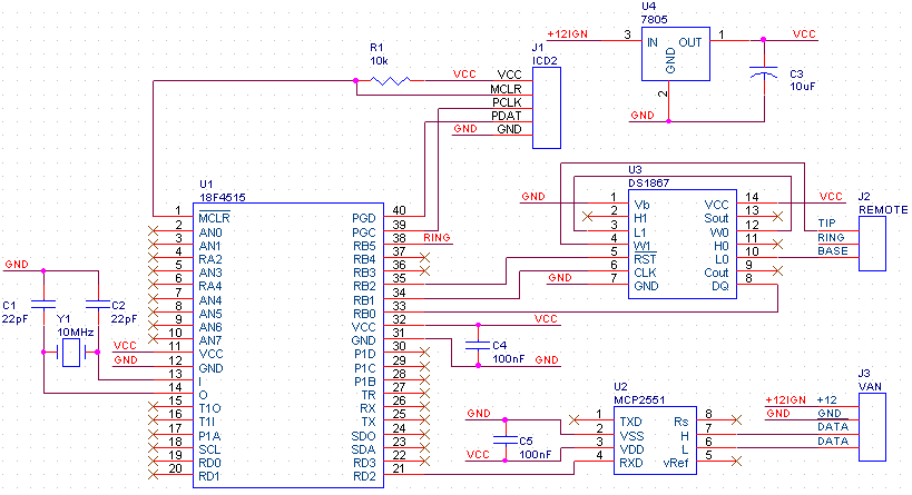
The design uses a Microchip MCP2551 CAN Transceiver to interface to the VANbus. The TTL level signals are provided to a pin of a Microchip PIC 18F4515 which is used to decode the VAN bit stream. A push of the volume, seek or source button causes a Maxim DS1867 Digipot (dual 50k) to set the appropriate resistance that the Pioneer head unit will decode as a button push.
The circuit is powered by the ignition switched 12V, this, ground and the two data lines are picked up from the ISO connector going to the head unit. The connection to the Pioneer head unit is through their standard 3.5mm stereo jack interface.
The source code for the PIC is not ready for release but for now I will make available van-pioneer.hex which is the firmware I currently use in my car. The code is unlikely to ever change because it's does the job I want it to with no problems.
UPDATE:
I have now updated the firmware to support mute/attenuate and folder/preset
up/down functions.
van-pioneer1.1.hex
Press vol up and vol down at the same time to attenuate or mute.
Roll the wheel up or down to change station preset or CD folder.
The ring of the remote jack has to be connected to RB5 of the PIC otherwise
rolling the wheel will just change track.
Pioneer Remote Input
The resistance presented between the base and tip of the jack is as per the following table:
| Resistance (Ohms) | Head unit button action |
| 2.2k | Source (power off with long hold) |
| 4.4k | Mute (Volume Attenuate) |
| 8.8k | Seek up* |
| 12.1k | Seek down* |
| 16.8k | Volume up |
| 23.6k | Volume down |
The other button actions that Pioneer head units seem to accept are listed below:
| Resistance (Ohms) | Head unit button action |
| 6.6k | List (Display) |
| 33.6k | Select |
| 48.6k | Mode |
These resistances are arranged so that a simple button interface can be made with a series chain of resistors. From ground (base of 3.5mm jack) take 2.2k, 2.2k, 2.2k, 2.2k, 3.3k, 4.7k, 6.8k, 10k, 15k. Then you can connect a button from each resistor terminal to generate the resistances listed above!
*Grounding the ring of the remote jack changes seek up & seek down into preset up & preset down.
VAN Packet
| Example Packet | 9C4C0080D4E2 | |||
| Splits into | 9C4 | C | 0080 | D4E2 |
| Section | IDEN | Flags | Data | Checksum |
| Meaning | Radio Remote Control | Write & Request ACK | No button pushed and wheel not moved | I couldn't be bothered to calculate this to check... :-p |
The important bit here is the data (0080) this is 16 bits of hexadecimal we can split this down into two 8 bit bytes:
0x00 contains the button states
0x80 is an integer representing the wheel position
First we split the button states byte (0x00) into bits
| Bit | 7 | 6 | 5 | 4 | 3 | 2 | 1 | 0 |
| 0x00 | 0 | 0 | 0 | 0 | 0 | 0 | 0 | 0 |
| Meaning when 1 | Seek+ | Seek- | ?wheel | ?wheel | Vol+ | Vol- | Source | ? |
The wheel integer starts at 0x80 being half way between 0x00 and 0xFF, the value increases as you roll the wheel up and decreases as you roll the wheel down. When you go past 0x00 or 0xFF the number returns to 0x80 and continues to move with the wheel but when the number is set back to 0x80 bits 4 and 5 in the button states byte change. I have not yet worked out the relationship but it would appear to be a mechanism to allow tracking of the number of wheel steps moved when rolling over the boundaries.
I have made the various datasheets available from my site but be aware these may not be as up to date as the manufacturers website:
MCP2551 CAN Transceiver (264kB)
PIC18F4515 Microcontroller (7MB)
DS1867 Dual Digipot (309kB)
My software if you are brave:
van-pioneer1.1.hex Code for PIC