| Back to Project Index | http://graham.auld.me.uk | E-Mail me |
| VAN Intro |
| USB VAN Monitor |
| Pioneer Headunit Control |
| VAN Line Protocol |
| VAN Frame Check Sequence |
| VAN Bus Packets |
Vehicle area network (VAN) is very similar to Controller area network (CAN), I'm going to assume that the reader has some knowledge of CAN as there's plenty of info on the web about that.
VAN uses a differential bus to remove the effect of common mode noise, the electrical signals are the same as CAN. Two wires are used, VAN-High and VAN-Low (also VAN+ VAN- but not to be confused with the VAN+ power supply line found in some vehicles), you can usually spot the two wires as they will often be twisted round each other.
VAN-H floats high and VAN-L floats low, this is the bus recessive state. Bus transmitters pull VAN-H down and VAN-L up to tranmit a dominant state. The dominant and recessive states on the pair of wires translate to a 1 or a 0 as detected by recievers
Recievers can be imagined as a simple subtractor. The voltage level on VAN-L is subtracted from VAN-H and the output of that subtraction is threholded to give a logical 1 or 0. Logic high or '1' is assosciated with recessive bits and no transmission, dominant transmission on the bus results in a logic 0 recieved.
Standard CAN line trancievers like the MCP2551 work quite nicely for VAN but as we will find out next, CAN and VAN use different data encodings on the line which stops us using CAN interfaces on a VAN bus.
VAN nodes all have their own clocks hence have to perform some level of clock recovery and synchronisation to accuratly sample data on the bus. Synchronisation requires the presence of a changing bit of data in order to have a edge to synchronise against. Imagine a message containing 20 zeros (or ones) significant clock drift over that time could not be corrected as the reciever would have no way of telling one zero from the next.
Manchester coding is a popular solution to this problem, each bit of data is encoded as either a positive of negative edge transition. This does have some drawbacks however, it has the potential to double the bandwidth required for the signal. VAN uses a method called Enhanced Manchester coding or (E-Manchester).
E-Manchester coding groups bits into nibbles (4 bits or half a byte). Every four bits has a fifth bit appended that is the logical inversion of the fourth bit. This has two benefits, firstly it guarantees a data transition every five bits for clock synchronisation and it provides some weak error detection capability.
Example: transmitting 0x8C
0x8C in binary -> 1000 1100
0x8C E-Manchester ->10001 11001
VAN data is broadcast on the bus in discreete frames of data encoded using E-Manchester that include an Identifier to allow recievers to filter the data they are interested in. Frame marking is made through the use of E-Manchester violations
This coding of every 4 bits by 5 bits makes length information a little ambiguous unless you remark on the codin (CAN is even more of a pain through the use of data dependant bitstuffing to enable clock recovery). For this reason I like to refer to Time Slices at this level, a Time Slice (TS) is the time taken to transmit a dominant or recessive bit on the bus in real time. Hence 4 bits take 5TS to transmit due to the E-Manchester bit being appended. A 125kbps VAN bus results in 1TS=8uS.
| Field Name | Length (TS) | Purpose |
|---|---|---|
| Start of frame | 10 | Marks start of frame, provides edges for clock synchronisation always 0000111101 |
| Identifier | 15 | Identifies the packet for recieve filtering, also provides priority in bus access arbitration, lower identifiers get higher priority bus access. 0x000 and 0xFFF are reserved |
| Command | 5 | These four bits, Extenstion (EXT), Request Acknowledge (RAK), Read/Write(R/W) & Remote Tramsmission Request(RTR) provide instruction to recievers. EXT is reserved and should be 1 (recessive), RAK set to 0 means that no acknowledge should be provided, R/W marks the frame as a read(1) or write(0) request, RTR set to 0 means the frame contains data, 1 means the frame contains no data and is a request to send. |
| Data | 0+ | 0-28 bytes usually but potentially up to 224 bytes of data |
| Frame Check Sequence | 18 | This is the CRC-15 of the identifier, command and data fields used to ensure the integrity of recieved data |
| End of Data | 2 | This transmits a pair of zeros which commit an E-Manchester violation marking the end of transmitted data. |
| Acknowledge | 2 | two recessive states, an acknowledge is given by one or more receivers transmitting a dominant state during the second state |
| End of Frame | 8 | 8 successive recessive states (1s) which mark the end of the frame |
| Inter-Frame Spacing | 8 | Not strictly part of the frame but there must be at least 8TS of recessive state between each frame on the bus |
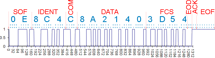
This example data was captured with a 'scope from a head unit removed from the car and decoded by hand.