Below are pictures taken while building TinyTrak3 kits with some extra modifications, any questions then please E-mail me at the bottom of the
page. All the pictures will bring up a higher resolution original when clicked
on if you want to see any parts in greater detail.
 |
 |
 |
 |
 |
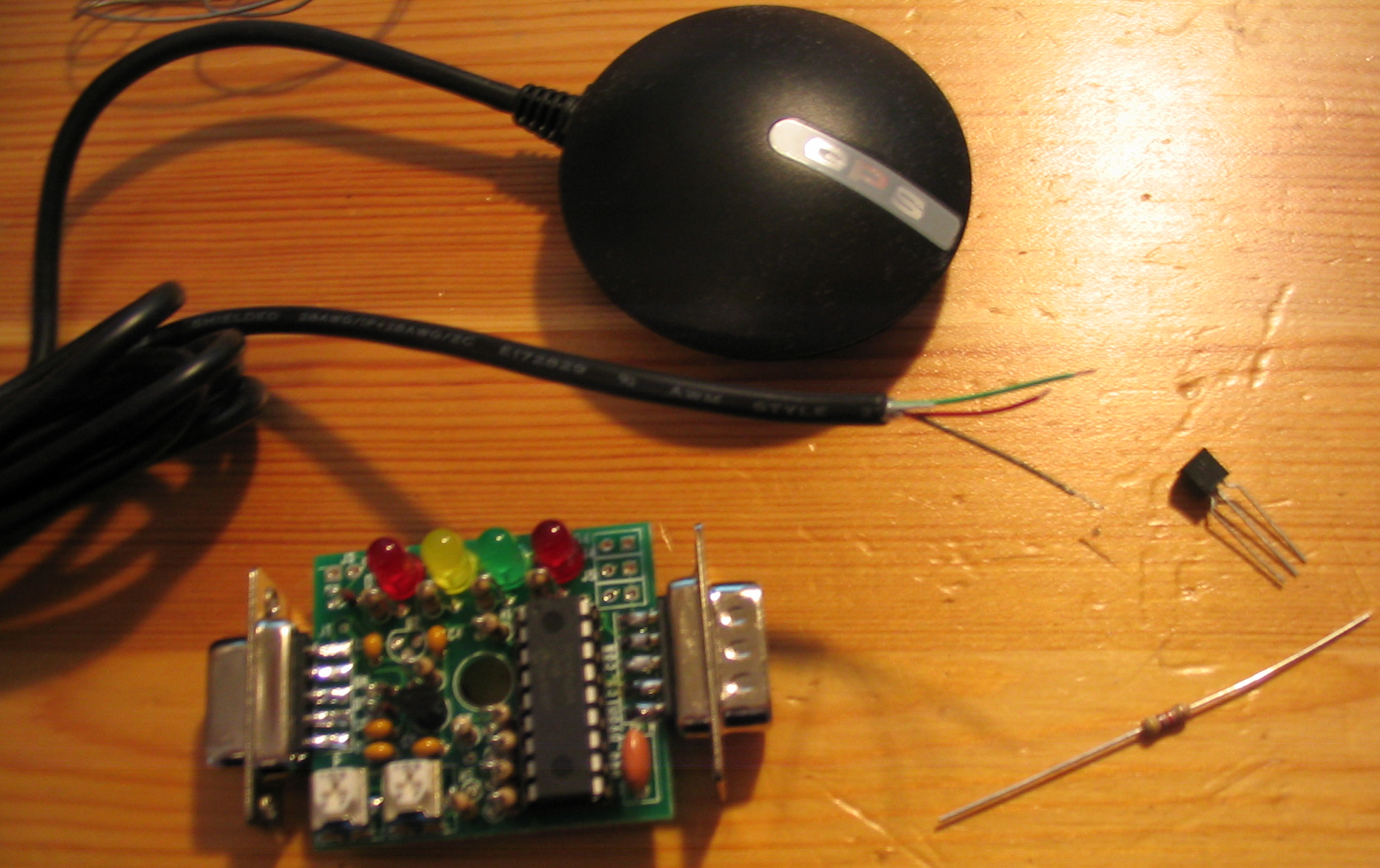
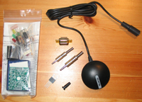
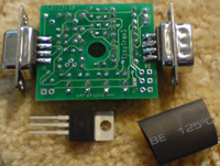
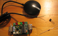
| TinyTrak3 Kit, GPS, upgraded voltage
regulator & connectors |
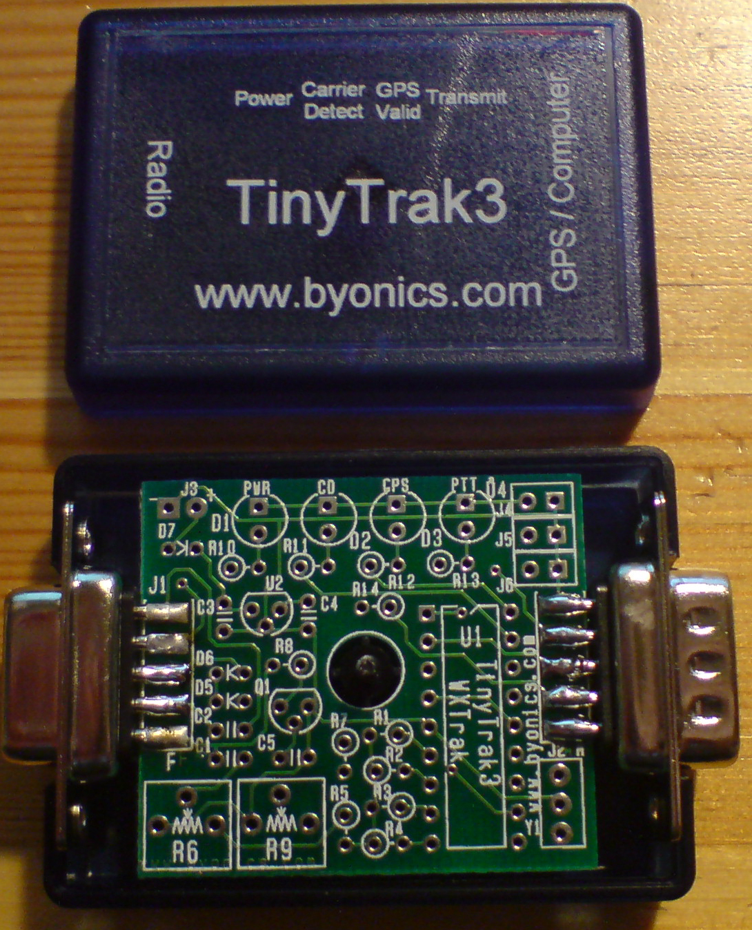
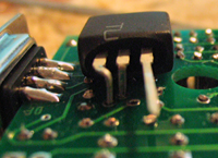
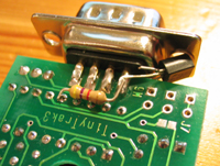
First I mounted the plug and socket
making sure they would hold the board firm in the case |
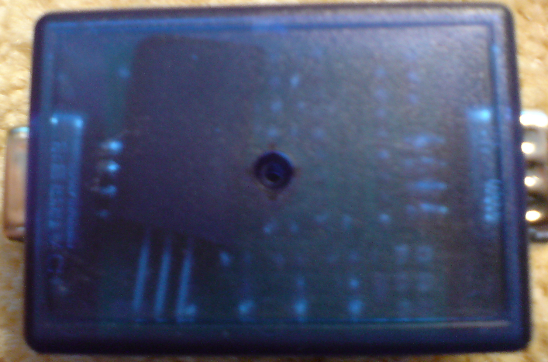
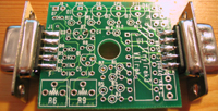
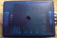
Testing box fit before going any further |
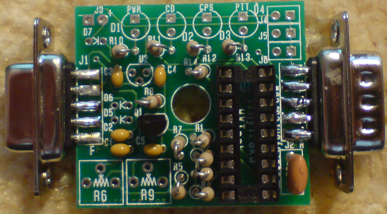
Half the TinyTrak components fitted |
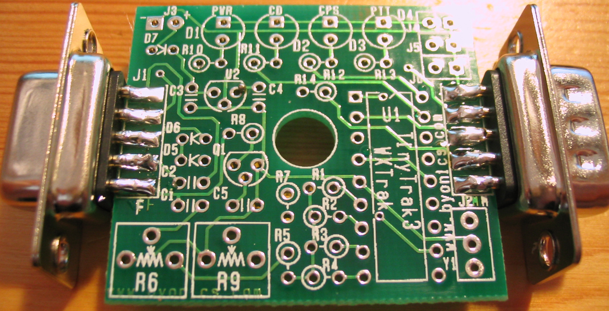
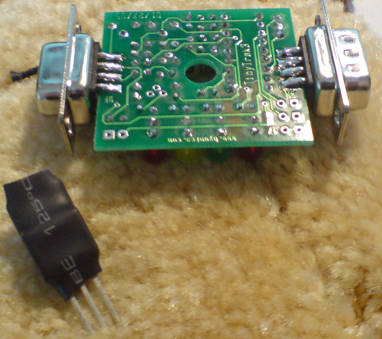
TinyTrak3 Built with no voltage
regulator and no microcontroller fitted. |
 |
 |
 |
 |
 |
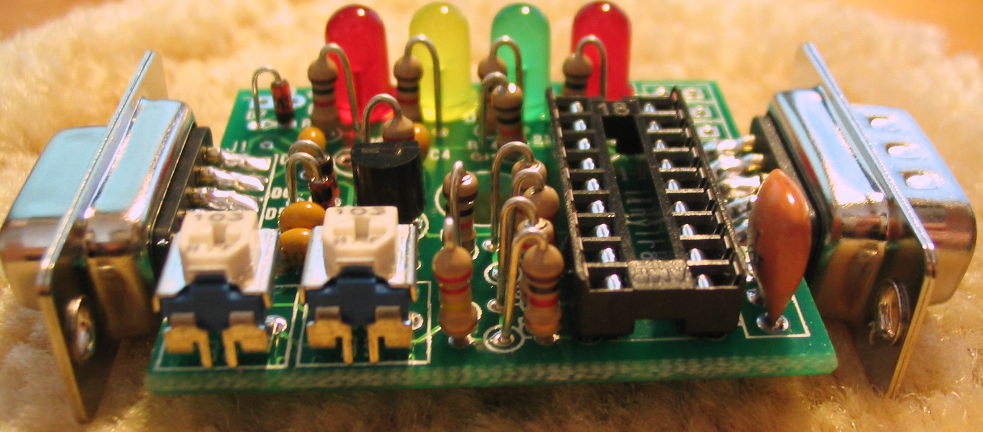
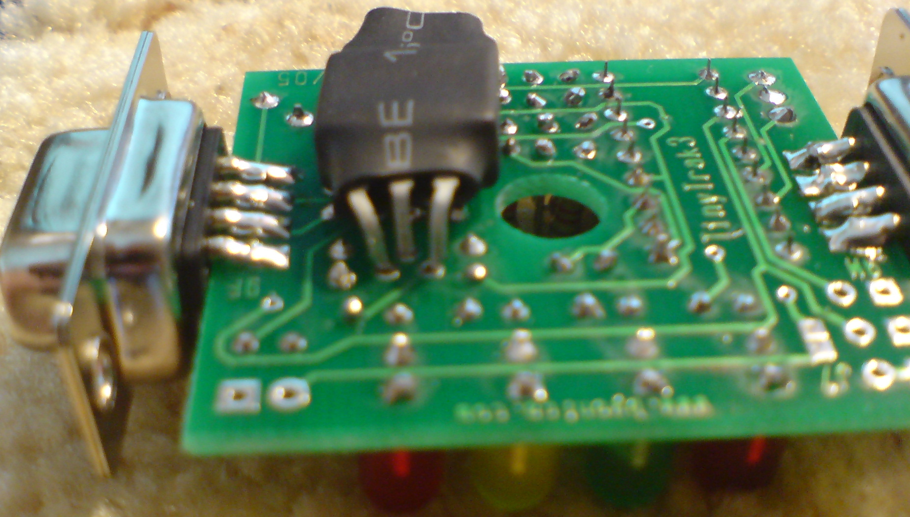
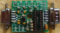
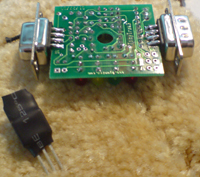
| Photographed from a more exciting angle |
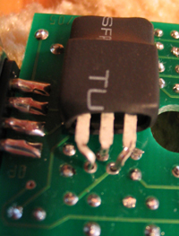
Larger voltage regulator to fit into box |
Heatshrink is used to insulate the
grounded tab of the regulator |
Possible placement of regulator |
Checking depth of the box to make sure
it will fit |
 |
 |
 |
 |
 |
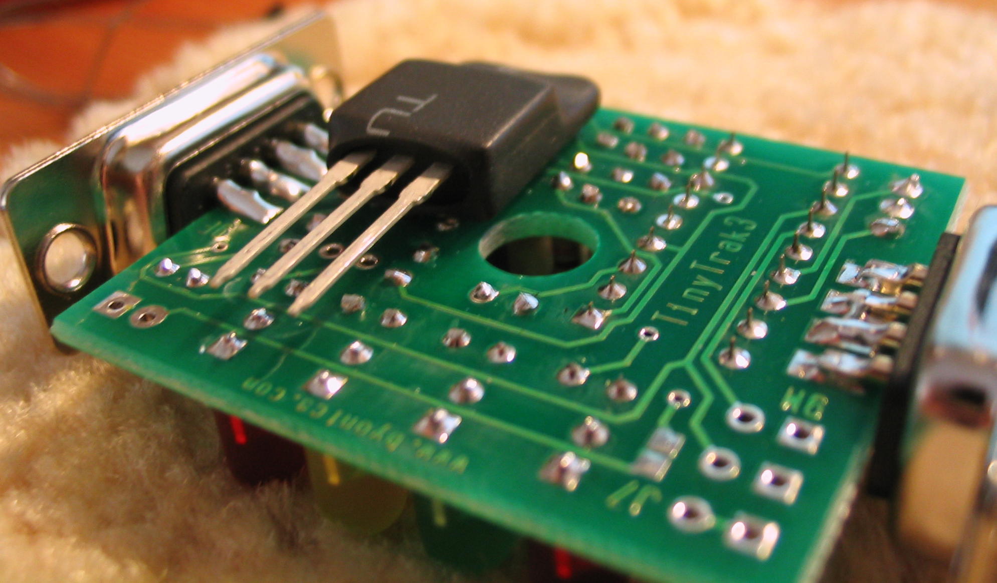
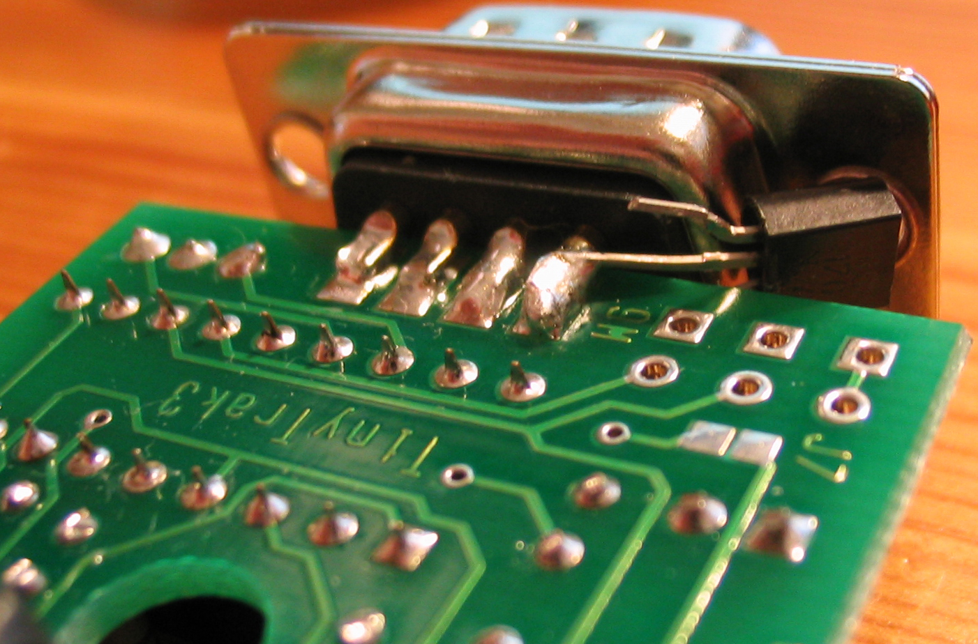
| The regulator pins need some
repositioning and shaping to fit |
2 of 3 pins positioned and shaped |
Pins sharpened to fit into current holes |
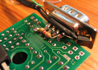
Carefully solder the regulator legs to
the PCB |
TT3 ready for GPS connection |
 |
 |
 |
 |
 |
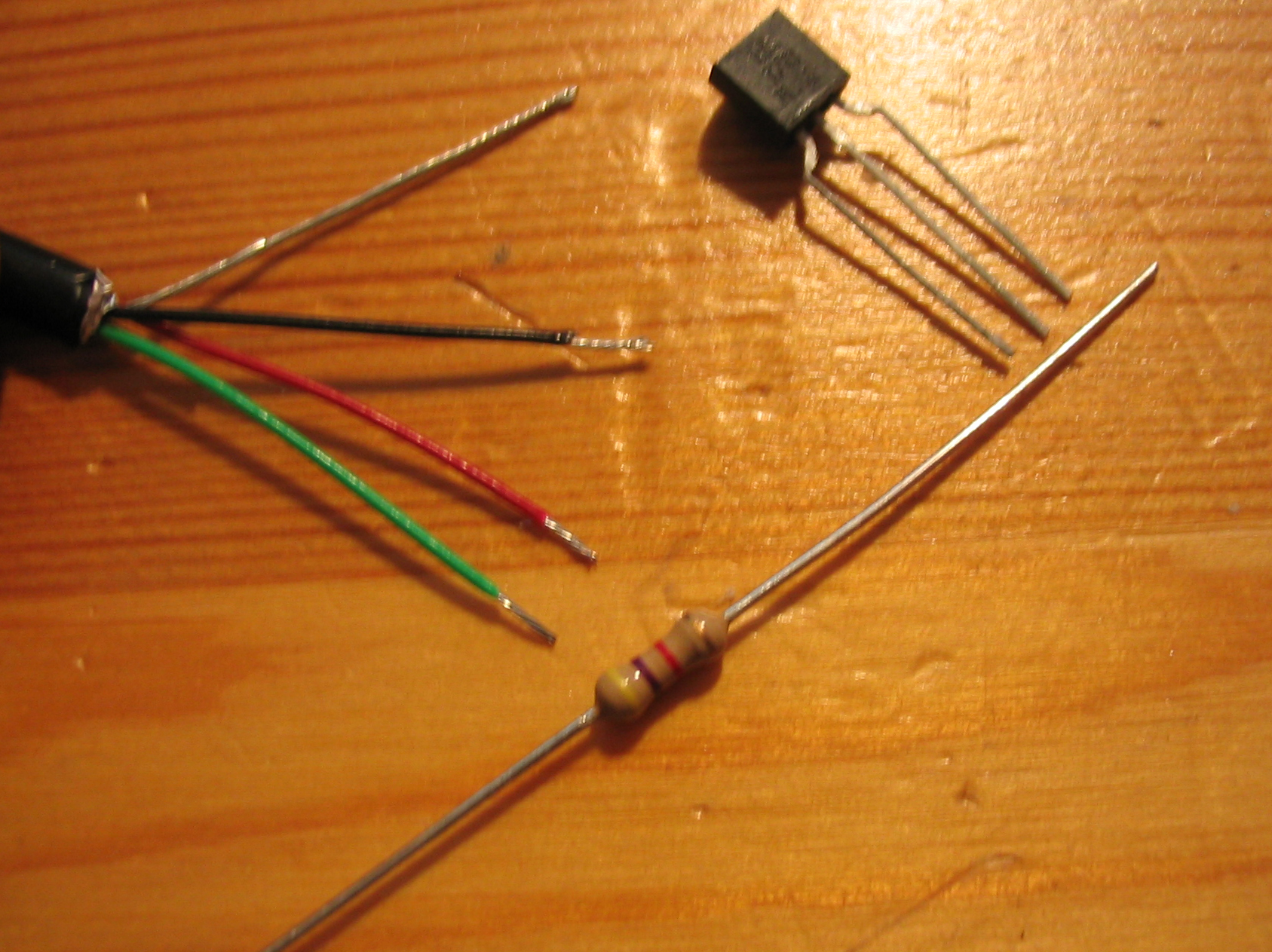
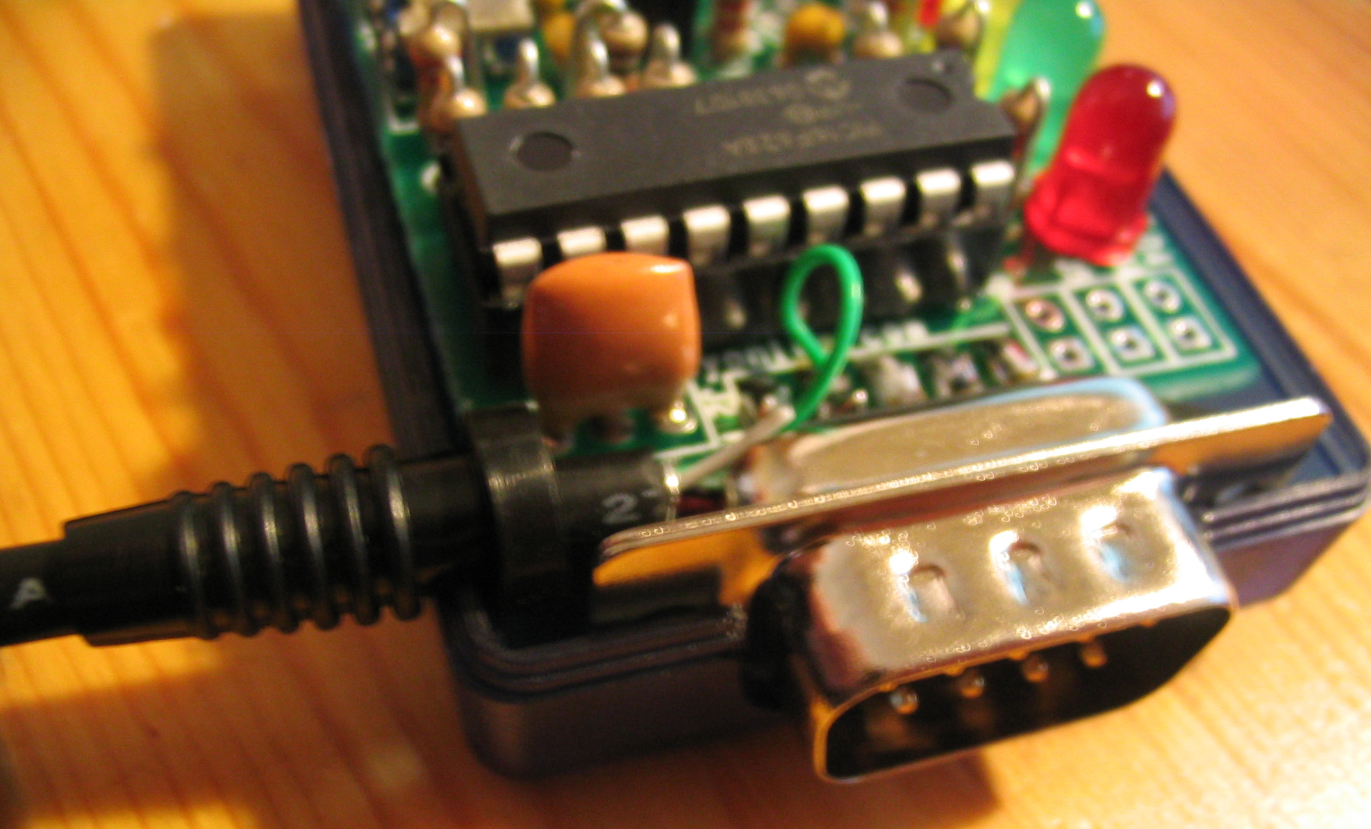
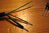
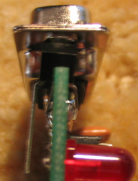
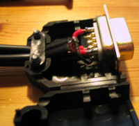
| FET & pull-up resistor for switching and
GPS cable end |
Heatshrink to insulate ground shield |
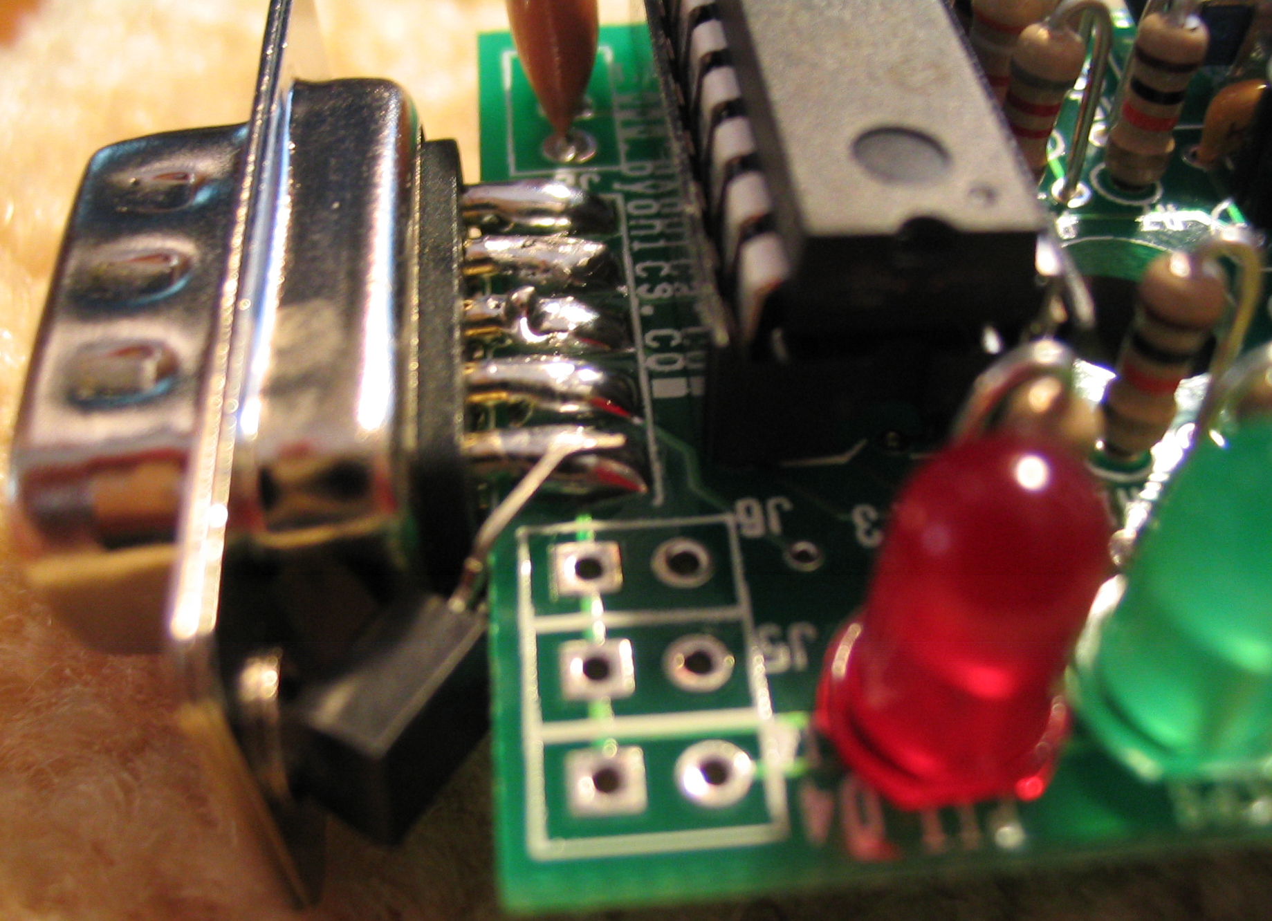
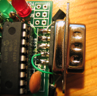
Positioning FET to contact pins 5 (GND)
and 9 (GPS off) |
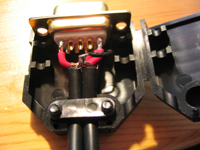
Shape leg for ground connection |
Shape gate leg for switching connection |
 |
 |
 |
 |
 |
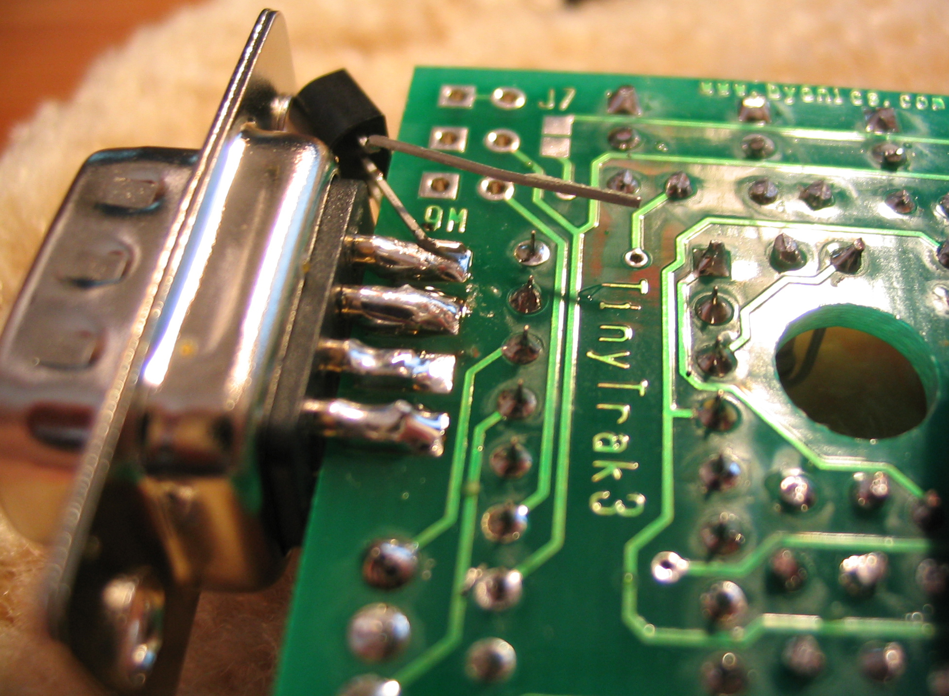
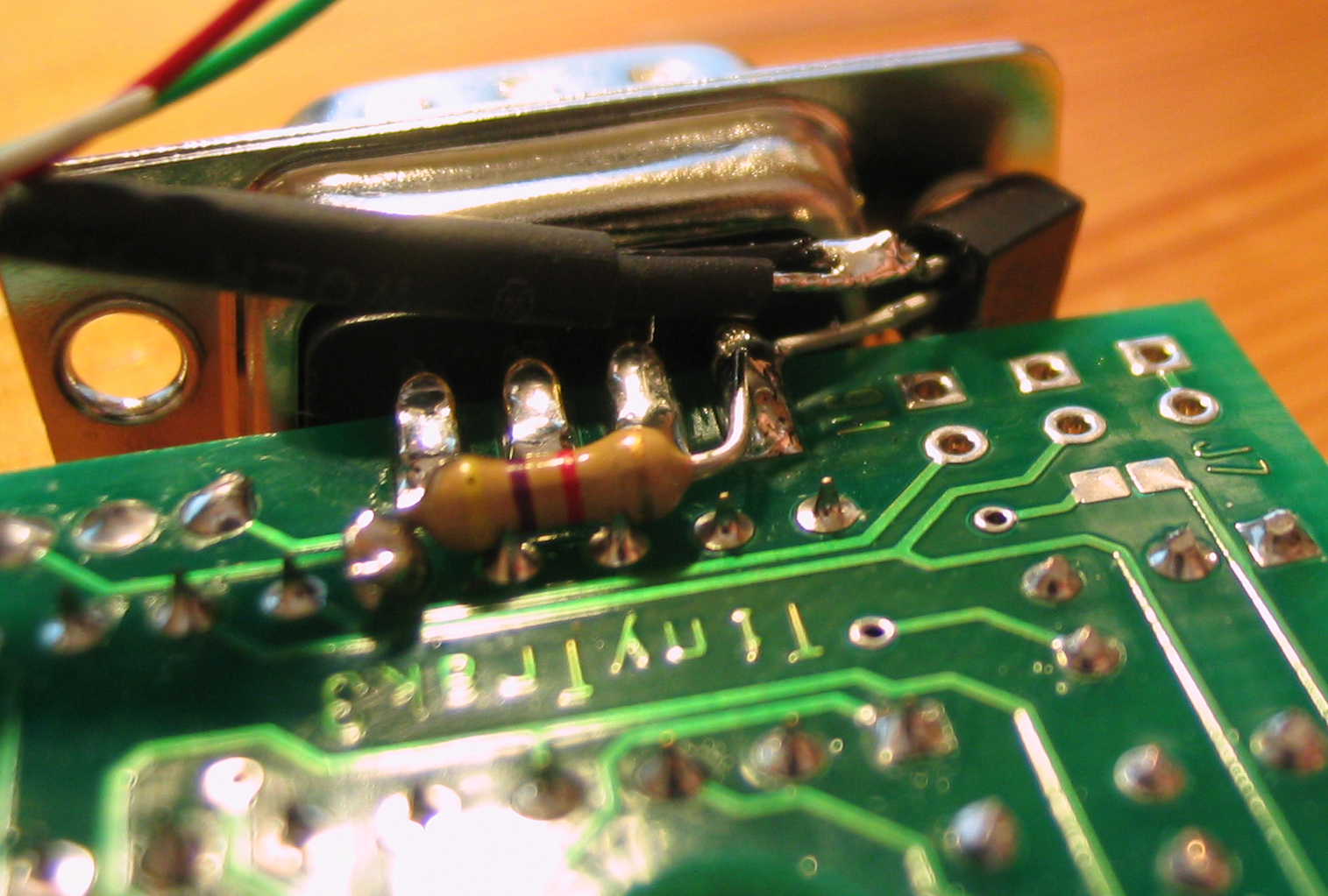
| Shorten leg so as not to short easily |
Position pull-up resistor from pin 9 to
the 5V MCU supply |
Connect grounds to FET and cover with
heatshrink |
GPS grounding arrangements prepared |
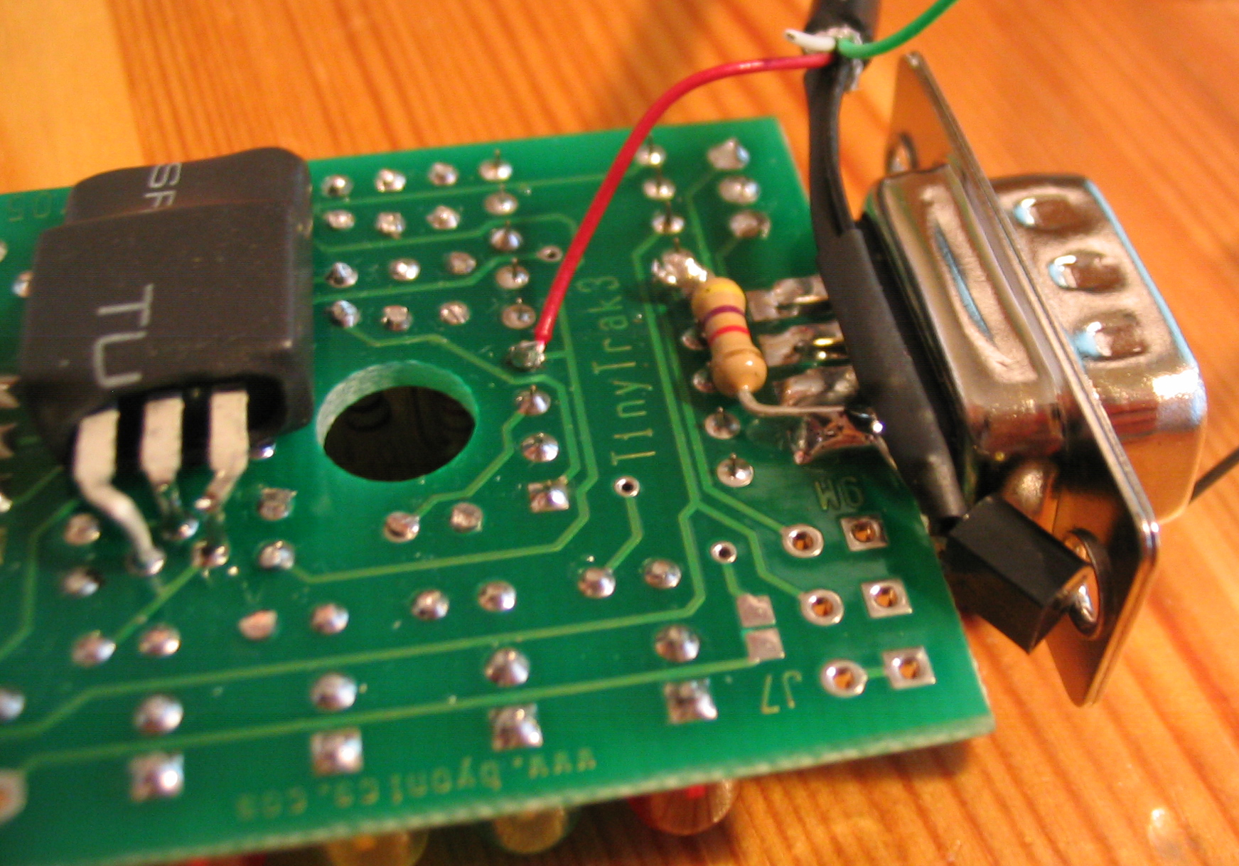
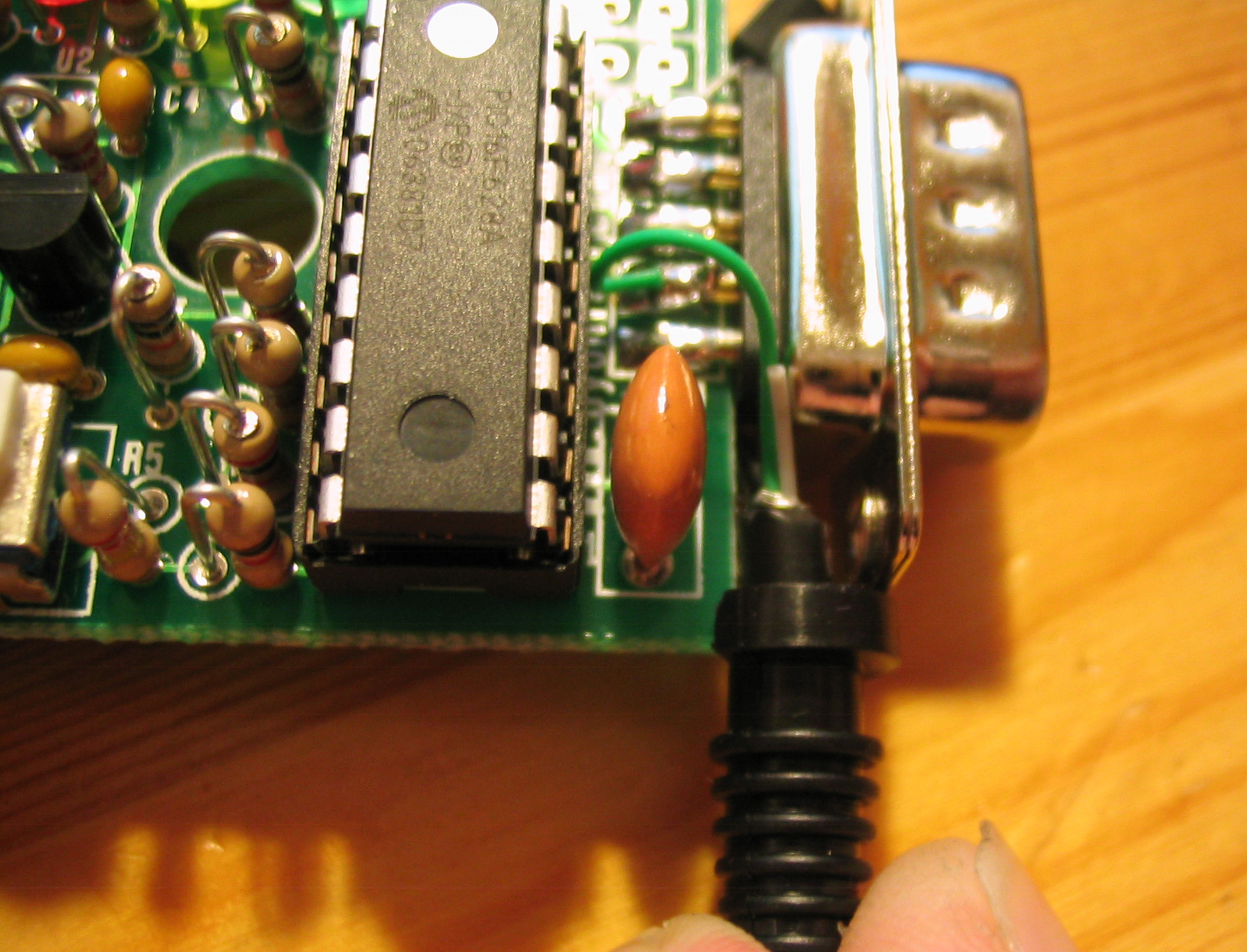
Connect GPS +5V power to 5V rail
supplying PIC MCLR |
 |
 |
 |
 |
 |
| Connect data out from GPS to pin 2 (data
in) |
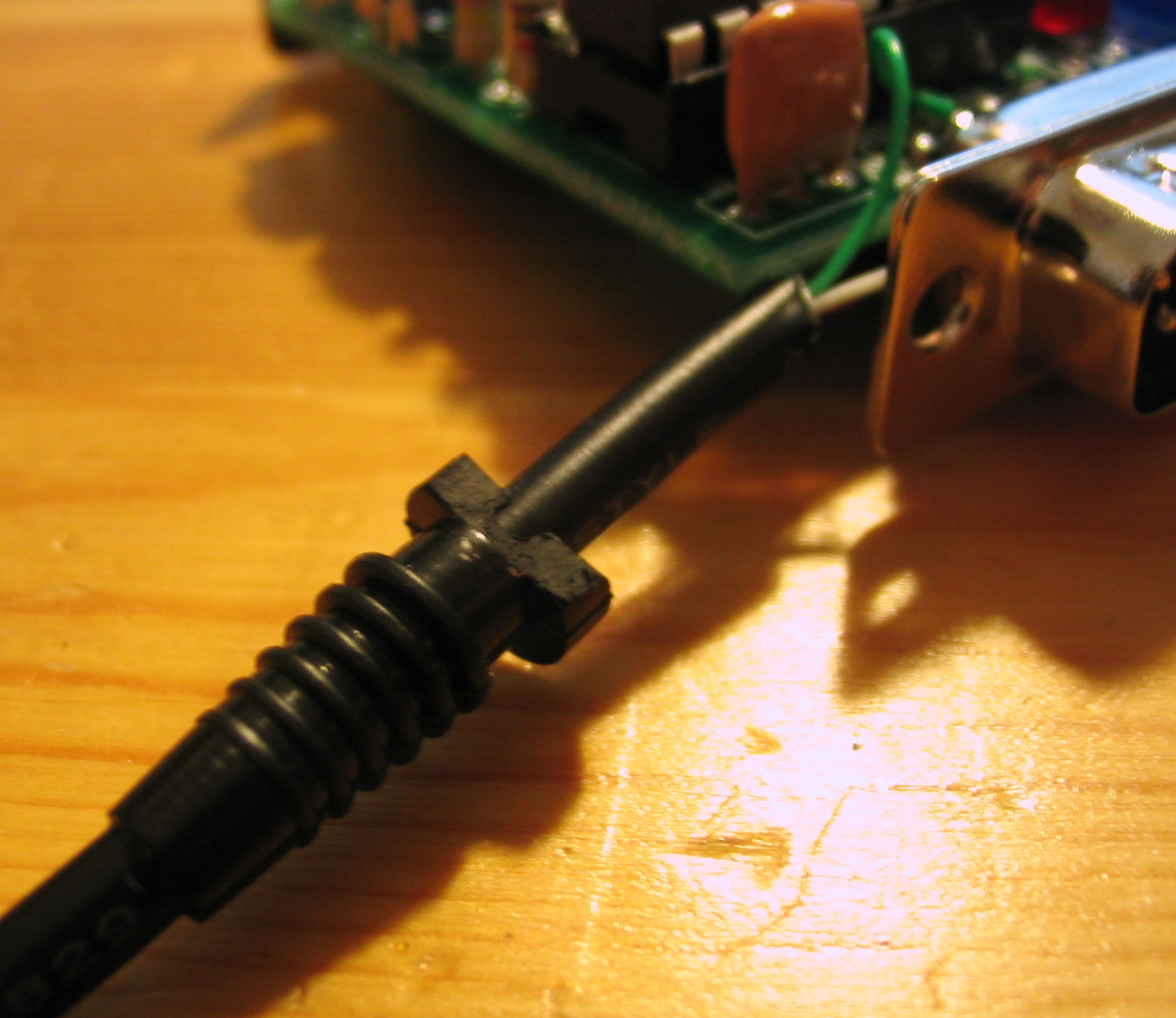
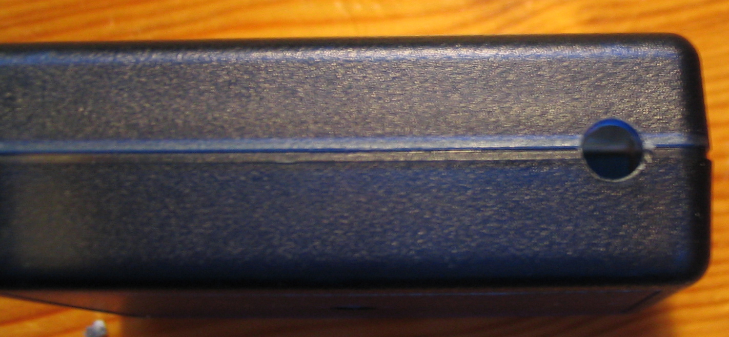
Chop edge of grommet to fit next to
board |
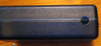
Positioning of grommet for cable exit |
4.5mm hole drilled in case |
GPS cable leaving box |
 |
 |
 |
|
|
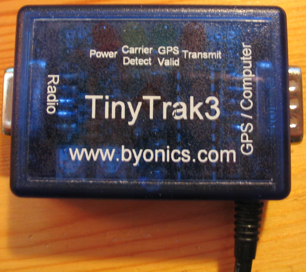
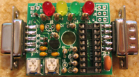
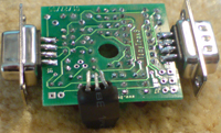
| Completed TinyTrak3 with 1A voltage
regulator and GPS |
Power and audio cable |
Power and audio cable, grounding
arrangement |
|
|