Below are pictures taken while building this interface box, hopefully these
along with the hardware info page will give you all the information you need to
build a similar device, any questions then please E-mail me at the bottom of the
page. All the pictures will bring up a higher resolution original when clicked
on if you want to see any parts in greater detail.
 |
 |
 |
 |
 |
| Connectors, USB hub & audio |
Connectors used |
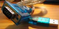
Original USB-serial adapter |
Box drilled for sockets |
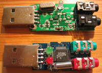
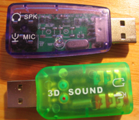
USB audio devices de-boxed |
 |
 |
 |
 |
 |
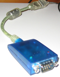
| FTDI chip USB-serial adapter |
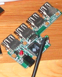
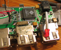
USB hub de-boxed |
USB audio devices |
Box used for project |
Extending the power LED |
 |
 |
 |
 |
 |
| Measuring up for connectors |
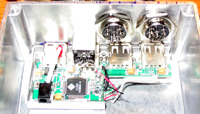
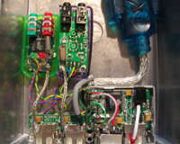
Rough layout of kit in box |
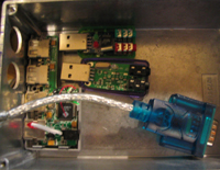
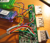
USB connections made |
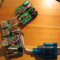
Connections to USB hub reverse |
USB ready for testing |
 |
 |
 |
 |
 |
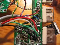
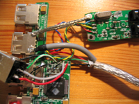
| Close up of sloppy soldering |
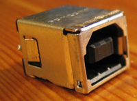
USB plug replaced with socket |
USB type 'B' socket |
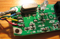
Replacing one USB connector |
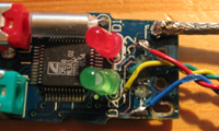
Don't break tracks desoldering! |
 |
 |
 |
 |
 |
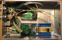
| Layout decided upon |
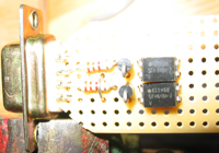
Serial RTS & DTR PTT |
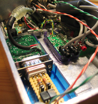
Kit mounted in box |
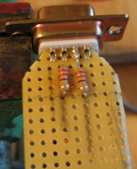
Building PTT interface |
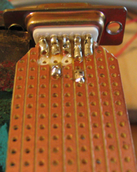
Veroboard soldered to plug |
 |
 |
 |
 |
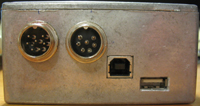 |
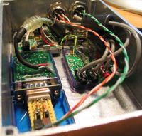
| Box from one end |
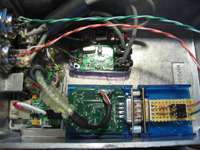
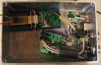
Box from above |
Laying out parts for glueing |
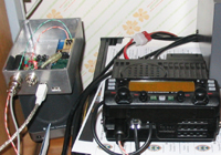
Test setup with radio |
The "completed" interface... |


