
| Back to Moixa Battery Index | http://graham.auld.me.uk | E-Mail me |
| GitHub - no project here yet |
Firstly we have the PCB - I've identified the various lumps, a couple of bits need verification, eg the switch and 6 pin header at the bottom. Handily it's not very compact, no parts on the bottom so items are logically grouped - e.g. the CAN interface for the battery looks like an ATMEGA interface for the CAN controller chip along with a USB to serial adapter which makes sense because the processor lump only has 3 UARTS, two appear to be used for stuff, there's probably one used for the console...
happily most significant parts are big enough to read and have identifiable markings, I've a little work to do with DVM and scope to wrap this up and develop a schematic showing pin connections to the processor board

I've started turning that into a block diagram showing interfaces guessed based on the specs of the parts identified - this will be refined further

GSM Module - SARA-G350 - Web Page Datasheet
USB to 4 UART - FTDI 4232HQ - Web Page Datasheet
1kb EEPROM - Microchip 93C46B - Web Page Datasheet
Microcontroller - Microchip PIC18F26k20 - Web Page Datasheet
Current Clamp Op Amp - Texas Instruments LM358 - Web Page Datasheet
RS485 line driver - Analog Devices LTC2854 - Web Page Datasheet
Wifi/Bluetooth - LM Technologies LM811 - Web Page Datasheet
USB-Parallel FIFO - FTDI FT240XS - Web Page Datasheet
Microcontroller - Microchip ATMEGA162 - Web Page Datasheet
CAN Controller - NXP SJA1000 - Web Page Datasheet
Isolator - Skyworks SI8422 - Web Page Datasheet
CAN line driver - TI SN65HVD232 - Web Page Datasheet
Real Time Clock/Calendar - NXP PCF8523 - Web Page Datasheet
Temperature Sensor - Microchip MCP9808 - Web Page Datasheet
Microcontroller - Microchip PIC18F24K22 - Web Page Datasheet
RS485 line driver - Texas Instruments SN65HVD75 - Web Page Datasheet
DC-DC converter - Texas Instruments LM5415 - Web Page Datasheet
Buffer - Texas Instruments SN74LVC2G241 - Web Page Datasheet
Watch Dog Timer - Analog Devices MAX6371 - Web Page Datasheet
LCD Touchscreen - Friendly Elec Matrix 2.8_SPI_Key_TFT 1706 - Web Page Wiki
Processor Module - NanoPi NEO Core - Web Page Wiki
Lots of testboards appear to just be connecting to unused pins on the processor module, a couple are actually useful
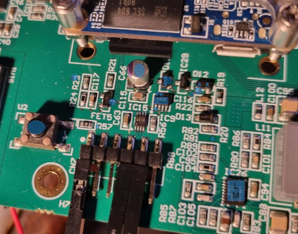
Worth of note on this board, there's an external WDT (IC9) it needs feeding every 60 seconds otherwise it briefly disables the DC-DC switcher in the power supply to reboot the board. The button (U2) directly disables the power while pressed and may as well be labelled reset. The WDT input is connected via a 1k resistor to Pin GPIOL11/IR-RX on the processor module. This is Linux GPIO pin 363 - handily that means it's not too tricky to write a little Bash script to keep the system alive.
CN7 down the bottom of the board contains the serial console, annoyingly you'll struggle to plug onto it without removing the PCB from the box - clip leads will help. Pin 1 (marked by the dot) is 0V/Gnd - Pin 4 is Rx and Pin 5 is Tx. You'll need a 3v3 level TTL serial interface - don't plug it straight up to an old RS232 D-type port or you'll be sad. Serial terminal set to 8N1 115200 Baud, you'll be rewarded by a linux console as root - not even a login required. The entire filesystem is mounted Read/Write so watch what you type.
This is all a bit unusual these days - you'd normally expect most production devices to have a password protected console or perhaps even the console disabled by default. You'd generally also have the root filesystem mounted Read Only but with an overlay filesystem to write changes to - that means if it all goes wrong your factory reset method can wipe the overlay partition and you'll have an as shipped device to just reconfigure. Hey ho - this makes life much easier for me!